Li-ion Battery
Published on: May 30, 2025
4 min read
Overview
I designed these batteries to replace our old LiPo solution for our club’s sailboat. Major issues we had were loose construction, exposed wiring and a lack of state of charge monitoring. My goal was to resolve these issues while maintaining battery capacity.
Since this was my first ever battery build, I agonized over design decisions and safety precautions. In the past we’ve had water enter the boat so water resistance and short-protection was a major priority. Ultimately, this was the parts-list I came up with:
Bill of Materials
| Item | Cost | Per unit | Purpose |
|---|---|---|---|
| x12 M50LT 5000mAh 14.4A 21700 Battery | $22.20 | $22.20 | Li-ion cells |
| Nickel Strip | $5.79 | $1.91 | Connecting battery cells in series/parallel |
| 3S BMS | $9.99 | $5.00 | Battery protection and cell balancing |
| PVC Heat Shrink | $12.99 | $1.30 | Battery pack insulation & protection |
| 16 AWG Wire Kit | $13.99 | $0.94 | Internal wiring |
| XT60 Waterproof Connectors | $12.99 | $1.95 | High-current waterproof power-in/out |
| $0.95 | $0.95 | USB-C power-in charging | |
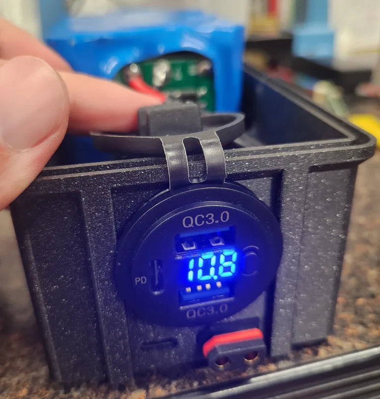
| Marine Voltmeter & USB Outlet | $12.99 | $12.99 | Voltage monitoring, USB-A/USB-C power-out |
| Fuse Kit | $11.69 | $1.17 | Overcurrent protection |
Total Cost: $81.37 | Per Unit: $48.41
This project can be made cheaper by buying individual components rather than bulk/kits. I opted to buy multiple to build up supplies for the club.
Design Choices
Why Li-Ion?
I weighed multiple different battery chemistries for our use-case. LiPo has a superb charge/discharge rate. LiFePO4 are relatively resiliant against water-ingress. But ultimately I chose Li-ion for these reasons:
- Our continuous draw is 3-5A with a likely max peak of 12A assuming all 3 servos stall simultaneously. This is still below what the 3S4P config could provide.
- Li-ion is very power-dense, and it would be easier to fit in the boat.
- There was an insane $1.85/cell sale, which made Li-ion very cost-efficient.
Why 3S?
I spec’d our battery voltage around our three servos, which take between 5-8.4V. Initially I considered doing a 2S configuration. This would let us run the servos off of the raw battery and eliminate losses from stepping down the voltage. However, 2S BMSs are exceedingly rare. Ultimately, I determined that it was not worth the minor loss in energy efficiency. Additionally, choosing a 3S config allows us to always run the servos at their max voltage. With this, we wouldn’t have to worry about the servo torque decreasing as the battery discharged.
Process
Pack Assembly
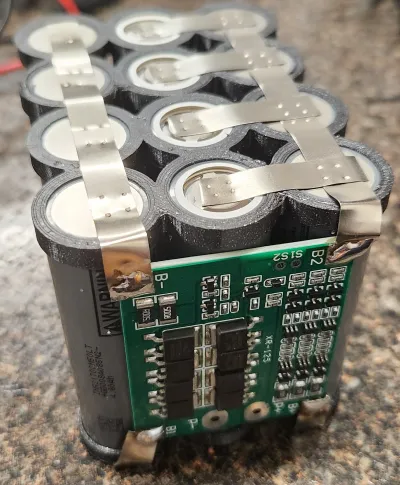
Fortunately the batteries all shipped at the same voltage, so I did not have to equalize their charges before connecting in parallel. To avoid damaging the cells, I opted to spot weld nickel strips between cell groups. I used 3d printed spacers to air gap the cells for best-practice. This helps prevent friction wearing of the insulation and reduces the likelihood of a short. To connect the BMS, I initially tried spot-welding again, but this led to poor adhesion. Instead, soldering directly to the pads worked much better.
Case
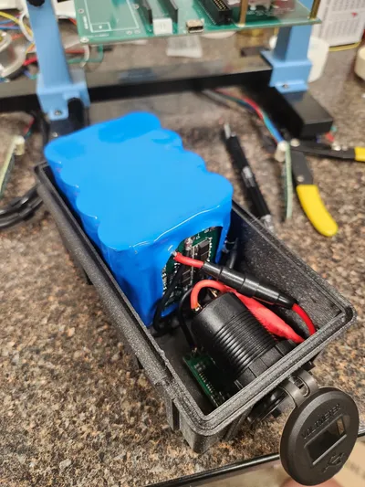
For the case I adapted a Parametric Box I found online. I dialed in the sizes of the battery pack and extruded holes for the XT-60, USB-C port and voltmeter in Fusion360. After a few single-layer test prints, I was able to get a good friction fit on all of the components. I then printed the entire case in PLA.
Wiring
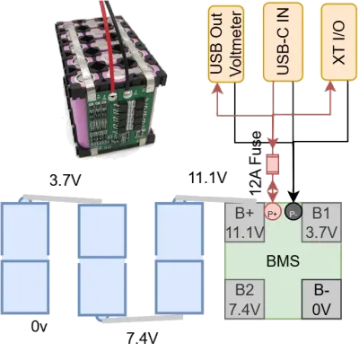
I diagramed the wiring out like so before soldering anything. The spacing between the pack and the case walls was tight so soldering the 16 AWG wire to the components was non-trivial. On the BMS, I branched the P- negative into 3 ground leads and the P+ into 3 wires after the fuse holder. The fit on the USB-C was somewhat loose, so I hotglued around the port to pin it in place.
Ultimately, all the components fit snugly within the case and the battery has been working great since!
What I Learned
-
Despite claiming 4A, the USB-C board charges the battery so slowly that I’ve opted to charge through the XT-60 plug exclusively. Going forward, using a USB-C PPS Trigger board would likely be more effective, although options are sparse as of writing.
-
The hinge on the parametric box eventually broke after a few months of use. There seems to be improved versions of the box online. Printing out of PETG would’ve also likely improved durability.
Resources
- Lithium-ion Battery Pack Guide: Incredibly helpful ‘one-stop shop’ for making your own battery pack.